User Tools
Table of Contents
Communication-Pattern Metamodel
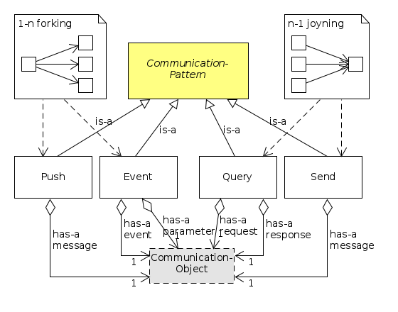
The RobMoSys communication patterns define the semantics in which software components exchange data over Services, e.g. via one-way “send”, two-way “request-response”, and publish/subscribe mechanisms on a timely basis or based on availability of new data. RobMoSys defines communication patterns to enable composability of services and components.
The general concept of a communication pattern originates from [Schlegel2004] where it is described in the context of the SmartSoft Framework in 2004. Since that, the there described communication patterns have been extended by several activities and have proven to be of generic use (see e.g. [UCM]). RobMoSys adopts a set of existing communication patterns (see below) that have proven to be relevant. For their definition, the wiki provides specific pointers to existing external documentation.
It is important to have a fixed set of a few communication patterns that efficiently support composition through unambiguous communication semantics and clearly defined communication interfaces. In addition, the mapping to different communication middlewares becomes possible over a generic middleware abstraction layer that is part of each communication pattern.
The communication pattern metamodel is depicted below. The name of an individual pattern (middle row of elements in the figure, e.g. send, query, push) refers to its definition in an external document as described in the remainder of this page.
Component Communication Patterns
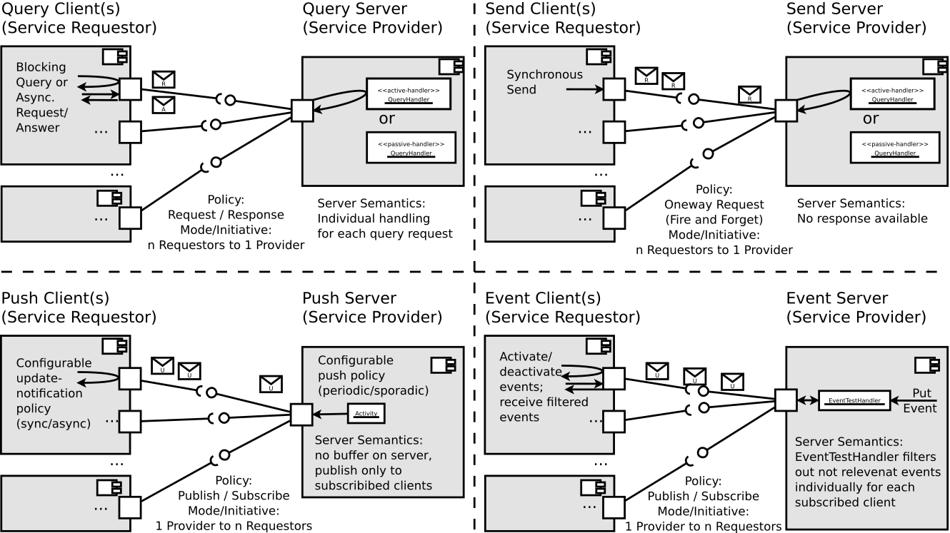
The four communication patterns (see table below) define the basic set of recurring communication semantics that proved to be sufficient for all robotics use-cases related to inter-component communication at the service level (for service level, see Separation of Levels and Separation of Concerns).
| Pattern Name | Interaction Model | Description | Definition |
|---|---|---|---|
| Send | Client/Server | One way communication | [Schlegel2004, pp. 85-88] |
| Query | Client/Server | Two way request/response | [Schlegel2004, pp. 88-96] |
| Push | Publisher/Subscriber | 1-n distribution | [Schlegel2004, pp. 96-99] |
| Event | Publisher/Subscriber | 1-n asynchronous condition notification | [Schlegel2004, pp. 103-112] |
The figure below provides a schematic overview of the communication semantics.
Coordination and Configuration Patterns
The four coordination and configuration patterns (see table below) provide recurring semantics that proved to be sufficient for robotics use-cases related to behavior coordination (coordination of software components at the lower / skill level of the robotic behavior by the sequencing layer; for layers in robotic behavior coordination see Architectural Pattern for Task-Plot Coordination (Robotic Behaviors)).
| Pattern Name | Interaction Model | Description | Definition |
|---|---|---|---|
| Parameter | Master/Slave | Run-time configuration of components, see [Stampfer2016] | see [Lutz2014], [Lutz2017] |
| State | Master/Slave | Lifecycle management and mode (de-)activation | see [Schlegel2011] |
| Dynamic Wiring | Master/Slave | Run-time connection re-wiring | see [Schlegel2004, p. 11] |
| Monitoring | Master/Slave | Run-time monitoring and introspection of components [Stampfer2016] | see [Lotz2011] |
Each component in a system should by default implement the slave part of each of the four patterns. In addition, there is typically one specific component per system that implements the master part of the patterns and that is responsible to centrally coordinate the robot behavior (the sequencer, see Architectural Pattern for Task-Plot Coordination (Robotic Behaviors) and for Component Coordinationfor further details).
Parameter
The Parameter pattern allows run-time configuration of components. The following links provide further details:
State
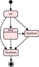
The state management of a component is one of the central patterns for run-time coordination of components. On the one hand, state management is about the generic lifecycle state-automaton (see figure on the right) that each component implements by default and that allows coordinated handling of the component's start-up and shutdown procedures as well as the component's fatal-error mode. In addition, component's individual run-time modes can be specified as explained in the following reference:
- Christian Schlegel, Alex Lotz and Andreas Steck, “SmartSoft - The State Management of a Component”, in Technical Report 2011/01, Hochschule Ulm, Germany, ISSN 1868-3452, 2011. PDF
Dynamic Wiring
Dynamic Wiring is used to increase run-time robustness and flexibility by dynamically changing the wiring between components. Additional details can be found here:
- Christian Schlegel. “Navigation and Execution for Mobile Robots in Dynamic Environments: An Integrated Approach”. Dissertation. University of Ulm, 2004.PDF
Monitoring
Run-time Monitoring and Introspection of components is an important aspect in robotics that requires dedicated interaction mechanisms. The following reference provides details of a concrete realization:
- Alex Lotz, Andreas Steck, and Christian Schlegel. “Runtime Monitoring of Robotics Software Components: Increasing Robustness of Service Robotic Systems”, in International Conference on Advanced Robotics (ICAR '11), Tallinn, Estonia, June 2011. IEEE-Link
RobMoSys Tooling Support
Tooling Support by the SmartSoft World
- The SmartSoft World is fully conformant to the RobMoSys communication patterns. The mapping of communication patterns in the SmartSoft World is described in
- Christian Schlegel and Alex Lotz, “ACE/SmartSoft - Technical Details and Internals”, in Technical Report 2010/01, Hochschule Ulm, Germany, ISSN 1868-3452, 2010. PDF
- The SmartMDSD Toolchain allows to use RobMoSys compliant communication patterns and also is an example of how to realize their metamodel with Ecore.
- The SmartTCL language conforms to the RobMoSys composition structures and can be used for Robot Behavior Coordination.
See Also
References
- [Schlegel2004] Christian Schlegel. “Navigation and Execution for Mobile Robots in Dynamic Environments: An Integrated Approach”. Dissertation. University of Ulm, 2004.PDF
- [Stampfer2016] D. Stampfer, A. Lotz, M. Lutz und C. Schlegel, „The SmartMDSD Toolchain: An Integrated MDSD Workflow and Integrated Development Environment (IDE) for Robotics Software,“ in Journal of Software Engineering for Robotics (JOSER), 2016, pp. 3-19. Link
- [UCM] Object Management Group (OMG). Unified Component Model for Distributed, Real-Time and Embedded Systems RFP (UCM). Document number: mars/2013-09-10. Sept. 2013. LINK.
- [Lutz2017] Matthias Lutz, “Model-Driven Behavior Development for Service Robotic Systems: Bridging the Gap between Software- and Behavior-Models,” 2017. (unpublished work)
http://www.robmosys.eu/wiki-sn-03/modeling:metamodels:commpattern


