Note: This is a snapshot of the RobMoSys Wiki as of June 23rd 2017.
Live Version for this page.
domain_models:navigation-stack:start
Flexible Navigation Stack
The flexible navigation stack is a set of components specifically related to provide a flexibly applicable navigation capability for a service robot. This navigation stack can be used on various robot platforms with different kinds of sensors and is able to deal with unstructured and dynamic environments of variable scale. The focus hereafter is to emphasize the general design choices and architectural decisions of the navigation stack components. After that, the following section provides some technical details and references for the concrete open-source components that can be used already now, e.g. with the Robotino3 platform.
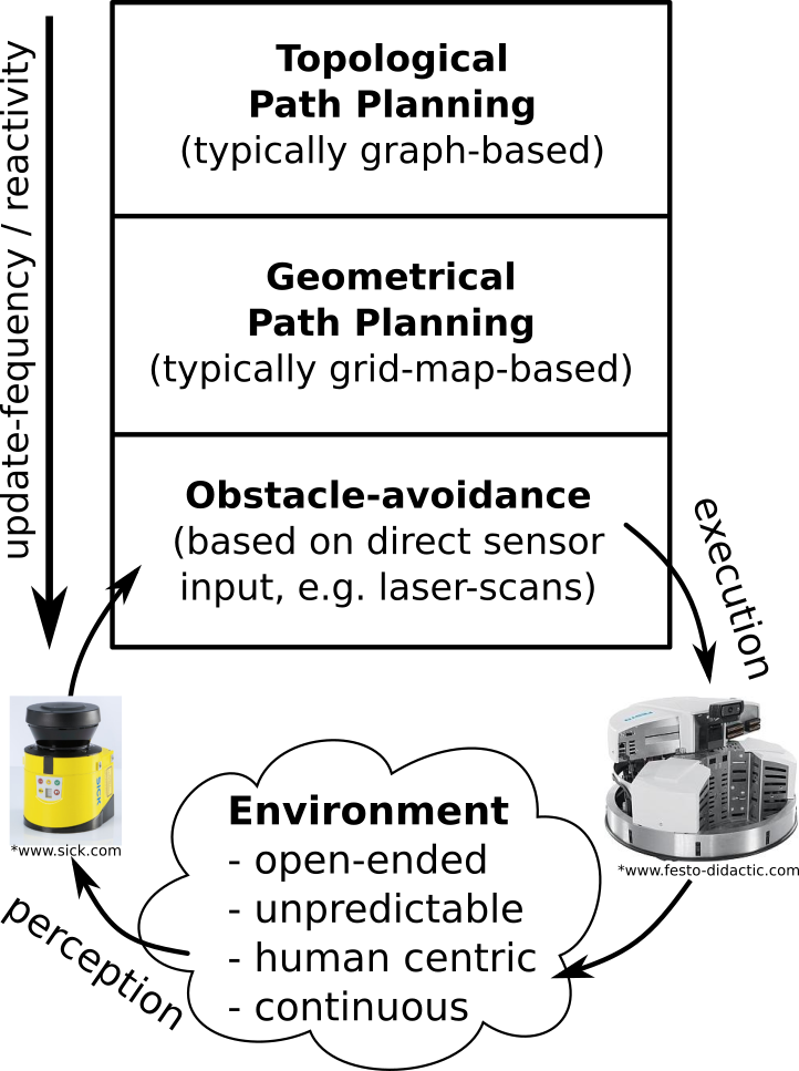
The figure on the right illustrates the three main levels of the navigation stack. These levels describe the shared responsibilities between different parts of the navigation stack. These responsibilities are assigned top down according to the subsidiarity principle (as explained next).
The bottom level defines components (a full list is provided further below) related to the fast and reactive obstacle-avoidance navigation loop. This loop ensures that regardless of where the robot has to move next, this movement will not cause a collisions and the robot will not be commanded to execute a physically invalid movement considering the robot's kinematic and dynamic constraints. Therefore this loop will only command navigation values that never lead to a collision even if these commands might not directly lead towards the next goal (e.g. because of the need to avoid a suddenly appeared obstacle in between). In consequence this loop might lead to a globally non-optimal, yet collision-free, navigation.
On the middle level, a geometric path planner calculates intermediate way-points based on a grid-map of the current environment. The planner relies on this map, which is updated during the navigation to accommodate for changes in the environment. Localization components need to estimate the current position of the robot within that maps. Several existing path-planning algorithms (using A* for example) allow the generation of intermediate way-points to be individually approached by the lower obstacle-avoidance level. In contrast to the lower obstacle-avoidance level, this intermediate geometric path planing level has a global view on the mapped environment. This is useful to e.g. avoid local minima (by generating intermediate way-points around them). It is worth mentioning that this intermediate level does typically not generate full trajectories (to be exactly executed by the lower level), but spares intermediate way-points. Sparse line of sight intermediate way points as a result from geometric path planning enables a clear separation of concerns between the two lower levels and avoids several disadvantages with respect to wasting resources (due to e.g. too frequent need for path re-planning) continuous velocity changes and too tight (i.e. inflexible and hardly exchangeable) coupling with the lower level.
In some cases, even the intermediate level is not sufficient. For instance, if a robot needs to navigate in an entire building consisting of several floors, maybe connected over elevators, then building a single huge grid map becomes complicated, too inefficient and too resource consuming. In these cases, it is rather reasonable to calculate several smaller grid-maps (e.g. one for each level or room in the building) and to concatenate these grid-maps in a topological map (which is typically a graph). The responsibility of this top level is to provide a logical plan how to navigate through the separated maps, e.g. through levels or rooms of a building.
The separation of the navigation components into these three levels has several advantages. The levels can be composed to individual navigation solutions best fitting the needs of the application or the current environment a robot is navigating in. According to these needs the size of the stack can be changed, with the bottom level being the most versatile and configurable one. For instance, some scenarios might require to manually command a robot using a joystick. In that case, both upper levels would be replaced by a simple joystick driver component, while the collision avoidance level still validates the navigation commands. In other scenarios, a robot might always navigate in a single map only. For that the geometrical path-planner on the middle level (without the topological path planner on top) is fully sufficient. Of course, there are also scenarios where all three levels are needed. Even in these latter cases, components on the individual levels can be flexibly exchanged (even at run-time, while moving) by alternatives because of a clear separation of responsibilities on each level and due to the clear interfaces between the levels.
The SmartSoft navigation components and the Robotino3 robot platform
The SmartSoft environment provides a set of flexible navigation components for all thee levels (as explained above). These components are ready for immediate use and can be downloaded from the SmartSoft Sourceforge repository. The following list of references provide documentation for the three core navigation components:
- SmartCdlServer: this is the main obstacle-avoidance component that uses the Curvature Distance Lookup (CDL)1) approach in its core
- SmartPlannerBreadthFirstSearch: this is geometrical path-planning component using a breadth-first-search algorithm
- SmartMapperGridMap: this component calculates up to date occupancy grid maps
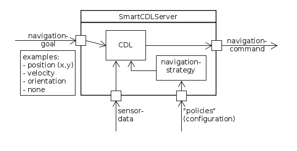
The SmartCdlServer component (see figure below) deserves some further explanations. In a nutshell, this component receives laser-scans and next goals (which can be either a position, velocity, orientation or even undefined). Based on these inputs, the internal CDL algorithm calculates a set of collision-free navigation-commands. Each of these navigation-commands is equally valid, the selection of one “appropriate” one is performed upon a configurable navigation-strategy. For example, one strategy might try to maximize the overall velocity, another might try to stay in the middle of a hallway, yet another strategy might try reaching the next goal closest possible (often the default strategy). This separation between the general obstacle-avoidance and the definition of different strategies adds flexibility with respect to applicability of this component in different scenarios.
There is a list of further components related to different sensor types and robot platforms whose generated documentation can be found here.
A packaged set of several components for immediate use, including those from the navigation stack with the Robotino3 platform can be downloaded from here.
Another application that uses this navigation stack in a structured and coordinated fleet environment using e.g. Robotino3 robots is described in the ETFA2016 paper2).
Moreover, as one of the further baselines in RobMoSys, the SmartSoft navigation components can be used with the PAL Robotics Tiago platform within the Gazebo simulation.
1)
Christian Schlegel. “Fast local obstacle avoidance under kinematic and dynamic constraints for a mobile robot”. In IEEE International Conference on Intelligent Robots and Systems (IROS). Victoria, Canada, 1998. DOI: 10.1109/IROS.1998.724683.
2)
Matthias Lutz, Christian Verbeek and Christian Schlegel. “Towards a Robot Fleet for Intra-Logistic Tasks: Combining Free Robot Navigation with Multi-Robot Coordination at Bottlenecks”. In Proc. of the 21th IEEE International Conference on Emerging Technologies and Factory Automation (ETFA), Berlin, September 6-9, 2016. Electronic ISBN: 978-1-5090-1314-2, DOI: 10.1109/ETFA.2016.7733602
domain_models:navigation-stack:start · Last modified: 2019/05/20 10:49
http://www.robmosys.eu/wiki-sn-01/domain_models:navigation-stack:start
http://www.robmosys.eu/wiki-sn-01/domain_models:navigation-stack:start
Page Tools

This project has received funding from the European Union's Horizon 2020 research and innovation programme under grant agreement No 732410.