User Tools
Table of Contents
Dependency Graphs
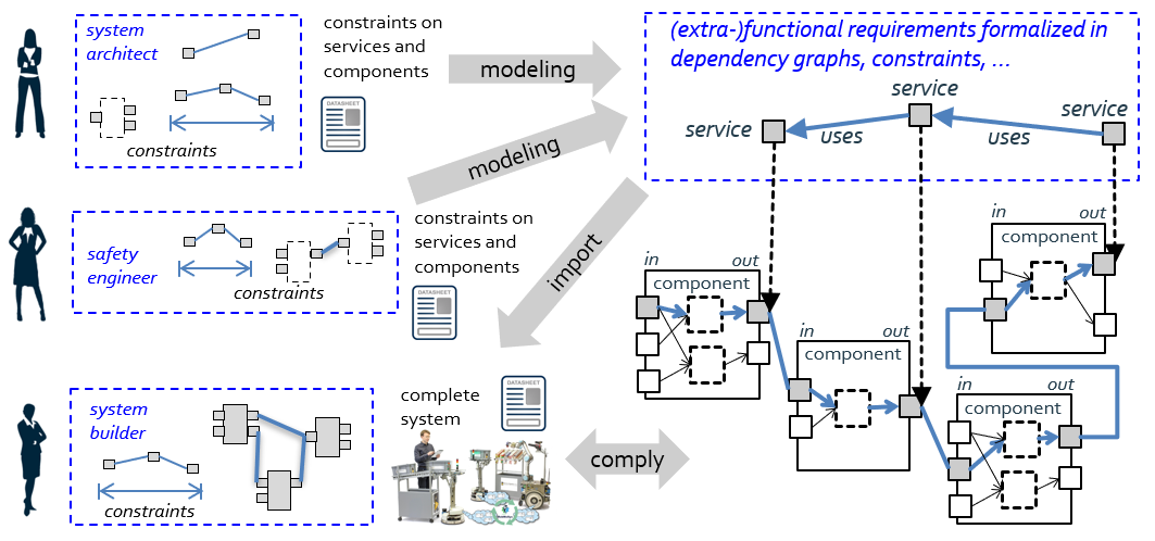
Dependency graphs can model system-level requirements that span across different components. Examples are properties along data flows, such as quality and aging of data, but also consistency aspects, triggering along computational chains and arrival time analysis.
A dependency graph can also be used to express requirements on data privacy, for example, “there must not be any link between a service providing a raw camera image and a service connecting to the network outside the robot”. A dependency graph can also express that, for example, the blur of a camera image depends on the speed of the robot. In order to keep the blur below a given threshold, one can derive the related maximum allowed velocity. A dependency graph can guide the system builder in selecting and configuring components according to the input from a system architect, a safety engineer and others. Thereto, the foreseen variation points, explicated in the data sheet, are exploited.
Dependency Graphs and System Composition
Dependency graphs can also be extracted from a virtual system composition (based on data sheets only, see above Figure). Before building the real system, one can already check whether the dependency graphs in the virtual system comply with the constraints of the dependency graphs representing the requirements. Tools can be used to try different configurations and to check for matches. In that way, dependency graphs also help to implement traceability from requirements to fulfillment by configurations of variation points. Dependency graphs also serve at runtime as sanity checks (before finally implementing a runtime decision) and for monitoring integrity.
Example: Dependency Graphs and Services
From a technical point of view, the meta-model of a dependency graph is again based on the entity-relation-model provided in layer 2 of Tier 1, which refines into different variants at layer 3 of Tier 1. The dependency graph shown in the above Figure is a simple one that expresses dependencies between services (entity service, relation uses). It gets checked by a mapping between the dependency graph and the graph resulting from the data sheet composition.
Example: Dependency Graphs and Error Propagation
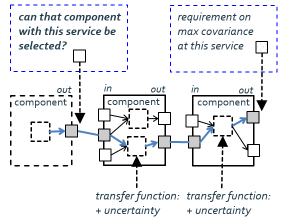
The Figure shows shows error propagation through a data flow across components. Transfer functions of a component specify what additional uncertainty comes on top. For example, the system builder can check whether the selected component is good enough to match the requirement at the end of the processing chain.
Example: Dependency Graph and Privacy Requirements
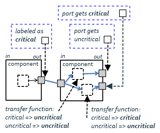
The dependency graph in the Figure is based on name/value pairs. The left component might be a service providing a camera image. That data is labeled as critical with respect to data privacy. The right component might provide a map based on the camera image (the transfer function for this port makes critical input to uncritical output) and the camera image enriched with pose information (critical input results in critical output at this port). Interval arithmetic and constraint solving are further mechanisms for dependency graphs.
RobMoSys Tooling Support
See also
* Cause-Effect-Chains are another example of Dependency Graphs.
http://www.robmosys.eu/wiki/composition:dependency-graphs:start


