Table of Contents
Managing Cause-Effect Chains in Component Composition
Composition can be found everywhere in a system and consider different aspects of that system. There is a general distinction between vertical composition (as e.g. demonstrated by the Service-based Composition) and horizontal composition. This wiki page describes an example of horizontal composition using “Cause-Effect Chains”.
While vertical composition addresses the combination of parts at different levels of abstraction (see Separation of Levels and Separation of Concerns), horizontal composition focuses on the combination of parts at the same level of abstraction. One example for the latter kind of composition is the definition of the so called Cause-Effect Chains for the purpose of refining specific system-level, performance-related, and non-functional properties. The following reference provides further details of this topic:
- Alex Lotz, Arne Hamann, Ralph Lange, Christian Heinzemann, Jan Staschulat, Vincent Kesel, Dennis Stampfer, Matthias Lutz, and Christian Schlegel. “Combining Robotics Component-Based Model-Driven Development with a Model-Based Performance Analysis.” In: IEEE International Conference on Simulation, Modeling, and Programming for Autonomous Robots (SIMPAR). San Francisco, CA, USA, Dec. 2016, pp. 170–176. LINK
In brief, the management of “Cause-Effect Chains” addresses the problem of combining different models of computation such as e.g. Synchronous Data-Flow (SDF), and Petri Net. That is, individual components typically specify parts of the overall, system-level models of computation by the definition of activities (i.e., the threads of that component). As the component should be used in different systems and different systems often require different models of computation, this component needs to be configured differently for each individual system so that a required model of computation is realized. Therefore, the activities of individual components are configured in a system so that the interaction of activities from different components are either directly linked (i.e., in a trigger relation) or loosely coupled (i.e., registers semantics). The constraint of a direct link is then mapped onto a related scheduling strategy (which depends on the capabilities of the used operating system).
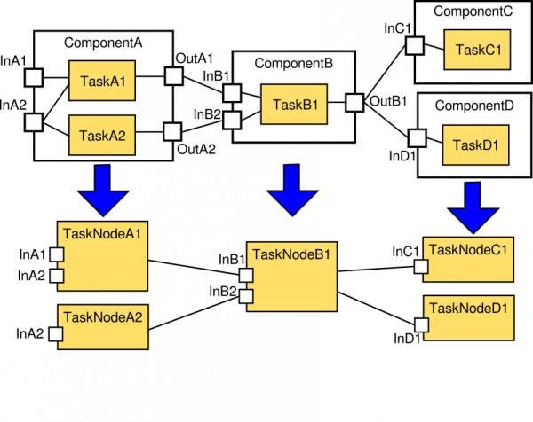
There is a relation between the System Component Architecture Metamodel (see also the System Builder Role and the System Configuration View) and the Cause-Effect Chain and its Analysis Metamodels (see also the Performance Designer Role and the Performance View). The figure above shows an illustration of models that demonstrate this relation. In particular, the Cause-Effect Chain metamodel (an example model is sketched in the lower half of the figure) removes component-boundaries by purpose to hide model-details that are not relevant for that modeling view. This results in a directed graph consisting of activity nodes (the orange blocks in the lower half of the figure) and abstract communication links. Consequently, an existing System Component Architecture model can be transformed into a Cause-Effect Chain model which again is enriched by further details related to refining the links between the activity nodes (i.e., specifying whether the links are loosely coupled or directly linked).
Moreover, the Component Definition meta-model enables the modeling of components with activities so that a component can be fully implemented and supplied to different system builders. The selected level of details of a Component Definition meta-model leaves the relevant aspects related to the specification of models of computation open for later configuration in different systems. As a result, existing components can be flexibly instantiated in different systems (conforming to the System Component Architecture Metamodel) and the configuration of components can be adjusted (conforming to the Cause-Effect-Chain and its Analysis Metamodels) without violating the component's internal implementation so that overall system-level requirements such as end-to-end delay demands, and CPU load requirements are satisfied for the current system under development. This management of Cause-Effect Chains is one of the leading examples for horizontal composition, providing a general mechanism that can be applied for other aspects of a system in a similar way.
Example Use-Case for Managing Cause-Effect Chains
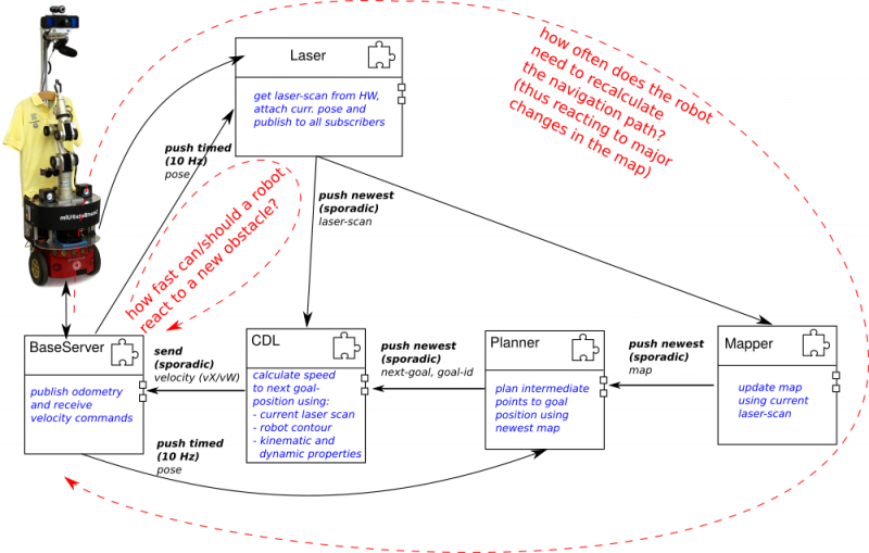
The figure below shows an example system derived from the Gazebo/TIAGo/SmartSoft Scenario consisting of navigation components altogether providing collision-avoidance and path-planning navigation functionality. This example is used in the following to discuss different aspects related to managing cause-effect chains which are again related to managing performance-related system aspects.
The example system in the figure above consists of five navigation components, from which two are related to hardware devices (i.e., the Pioneer Base and the SICK Laser) and the other three components respectively implementing collision-avoidance (i.e., the CDL component), mapping and path-planning. As an example, two performance-related design questions are introduced in the following with the focus on discussing the architectural choices and the relevant modeling options:
- How fast can a robot react to sudden obstacles taking the current components into account?
- How often does the robot need to recalculate the path to its current destination (thus reacting to major map changes)?
RobMoSys Modeling Support
RobMoSys Tooling Support
- The following page discusses the concrete models of this example using the SmartMDSD Toolchain: Example Use-Case for Managing Cause-Effect Chains in Component Composition using the SmartMDSD Toolchain
See also:
http://www.robmosys.eu/wiki-sn-02/composition:cause-effect-chain:start


