Table of Contents
Getting Started With Papyrus4Robotics
Installation
Papyrus4Robotics is distributed as a self-contained Eclipse RCP.
The RCP for your OS (64bits) is available from the links below:
To install it, just unpack the RCP archive in a directory of choice.
To run it, make sure that you have a Java 8 or newer JRE/JDK. Then just launch the papyrus-robmosys executable.
Running an Example
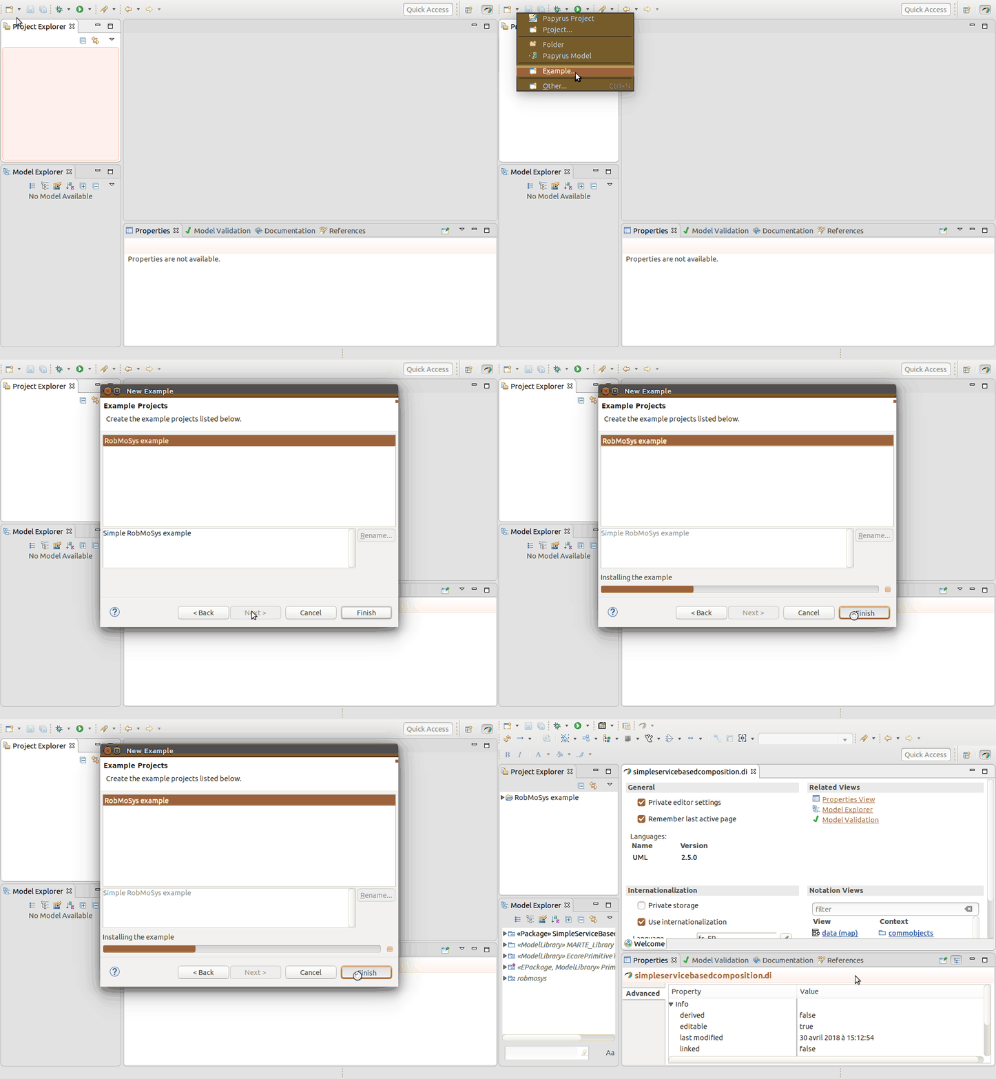
Papyrus4Robotics comes with an installed example to get you started. To run the example, just click New→Example and accept the default propositions in the wizard.
The Example Explained
Introduction
This example shows how Papyrus4Robotics supports the service-based approach for the composition of software components.
Composition in an Ecosystem organized in tiers is the approach adopted by RobMoSys to system integration. Next sections discuss how tier 2 and tier 3 participants use Papyrus4Robotics to model a simple service-based composition of a mapper component and a planner component.
The illustration below corresponds to the role descriptions, as taken from the RobMoSys wiki.
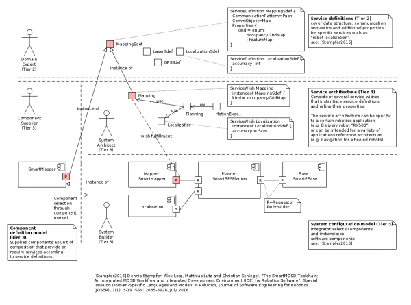
Domain Expert (Tier 2)
Tier 2 are robotics experts who define a complete characterization of services in robotics domains, e.g., mapping, planning, localization, etc. Tier 2 structures each robotics domain by creating domain-models that cover a number of aspects, including data structures and communication semantics. Service designers are the domain experts on Tier 2 that design individual service definitions for use by Tier 3.
The picture below shows a portion of data structures defined for the mapping domain in this example.
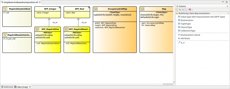
Papyrus4Robotics leverages concepts from OMG's MARTE NFP and VSL profiles to comply with RobMoSys' specifications on digital data representation. Built-in type definitions can be imported from the BasicNFP_Types MARTE library and specialized for a specific domain by using a dedicated palette (right side of the picture). Leveraging on MARTE, Papyrus4Robotics supports physical units descriptions to formally define unambiguous semantics of units of measurements in data types.
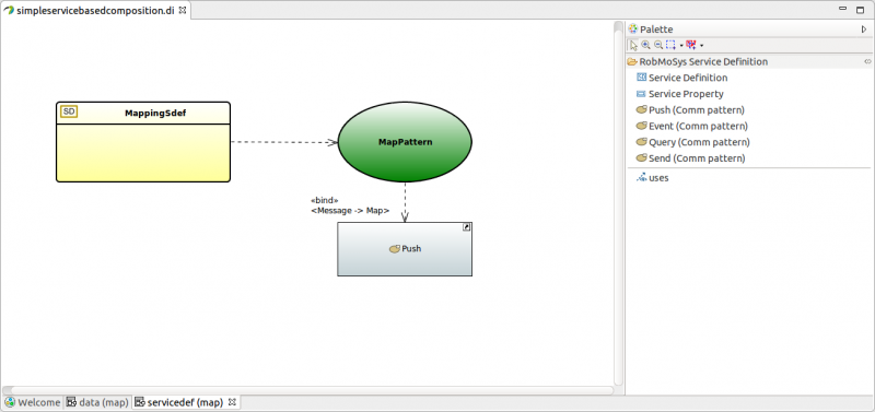
Once the communicated data structures (Communication Objects, identified with the CO icon on the top left corner) are defined, the communication pattern usage can be formalized. The next picture shows the model that describes the MappingSdef service. In this example, MappingSdef uses the Push pattern and selects the Map data type as communicated data structure.
Component Suppliers (Tier 3)
Component suppliers at Tier 3 provide models of software component definitions.
AcmeMapper
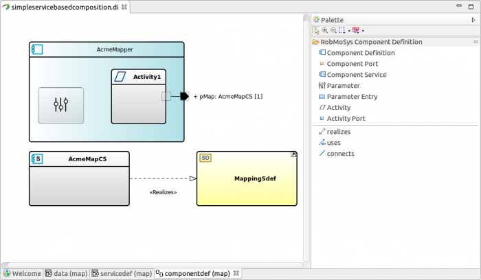
The model below shows a mapper component developed by a company called AcmeCorp (hence AcmeMapper), which provides a fully compliant implementation of the MappingSdef service definition above.
The example focuses on the modeling of a single component port (pMap) providing the mapping service. Aligned with the standard UML rules of interface realization, this is achieved by assigning the port a ComponentService item as a type (AcmeMapCS) that realizes MappingSdef.
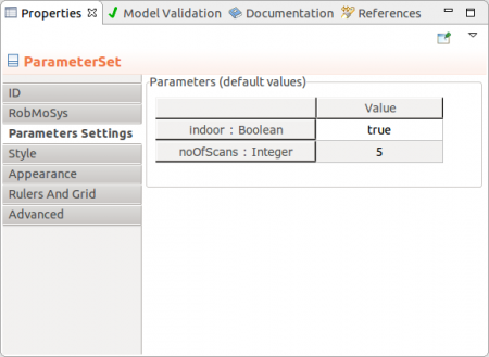
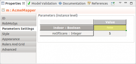
AcmeMapper contains one Parameter structure, that represents a set of parameters that make the component configurable for reuse in different scenarios by the system builder or even at run-time. The Parameter structure content is visualized in the model editor by selecting the Paramter icon and the Parameters Settings tab in the property view (see below).
In this simple example, AcmeMapper has 2 configurable parameters with built-in types. However composite value specifications (collection, tuple, choice, etc.) can be specified as well, using the MARTE VSL syntax.
AcmeMapper defines one activity (it could define more), which is a OS-agnostic representation of a thread. Activities provide wrappers for functions (algorithms). Activities do have set of parameters for configuration (e.g., interarrival range, that is max and min activation frequencies). Similarly to component parameters, activity paramters can be viewed and set through the Parameters Settings tab in the property view.
EmcaPlanner
The model below shows a planner component developed by a company called EmcaInc (hence EmcaPlanner).
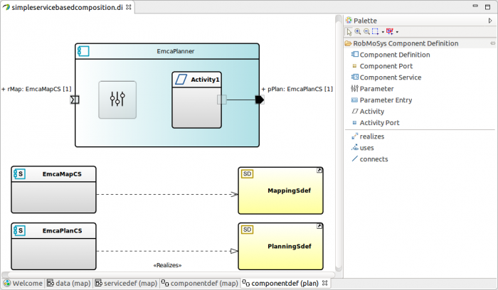
The example focuses on the definition of two component ports. pPlan provides a implementation of PlanningSdef (a planning service definition model not discussed in this document). rMap requires a fully compliant implementation of MappingSdef. To model the service requirement, in agreement with the standard UML rules, the usage item is used to create a dependency between the EmcaMapCS and MappingSdef.
System Builder (Tier 3)
System builders instantiate component definitions to provide a platform-independent specification of a software system. The model below shows the instantiation and connection of one instance of AcmeMapper and one instance of EmcaPlanner.
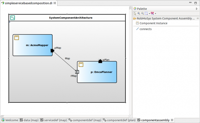
It is now assumed that the mapper component instance must work outdoor. The default configuration of AcmeMapper component definition was indoor, so the component instance m must be re-configured by the system builder.
For a component instance the parameter set is accessible by clicking on the instance itself and selecting the Parameters Settings tab in the property view. The next picture shows the value of indoor parameter is set to false. Yellow highlighting visually enforces the message that the parameter value is now different from the default one.
Conclusions
This example shows a structural model in the context of composition of software components. It shows how different tiers contribute models to achieve composition of software components, using service-definitions as central architectural element for it. Then it focuses on one instance of the mapper component and shows a simple reconfiguration of one of its parameters.
Do It Yourself
This section is in progress. More content will be added shortly.
Connect ComponentInstance Items
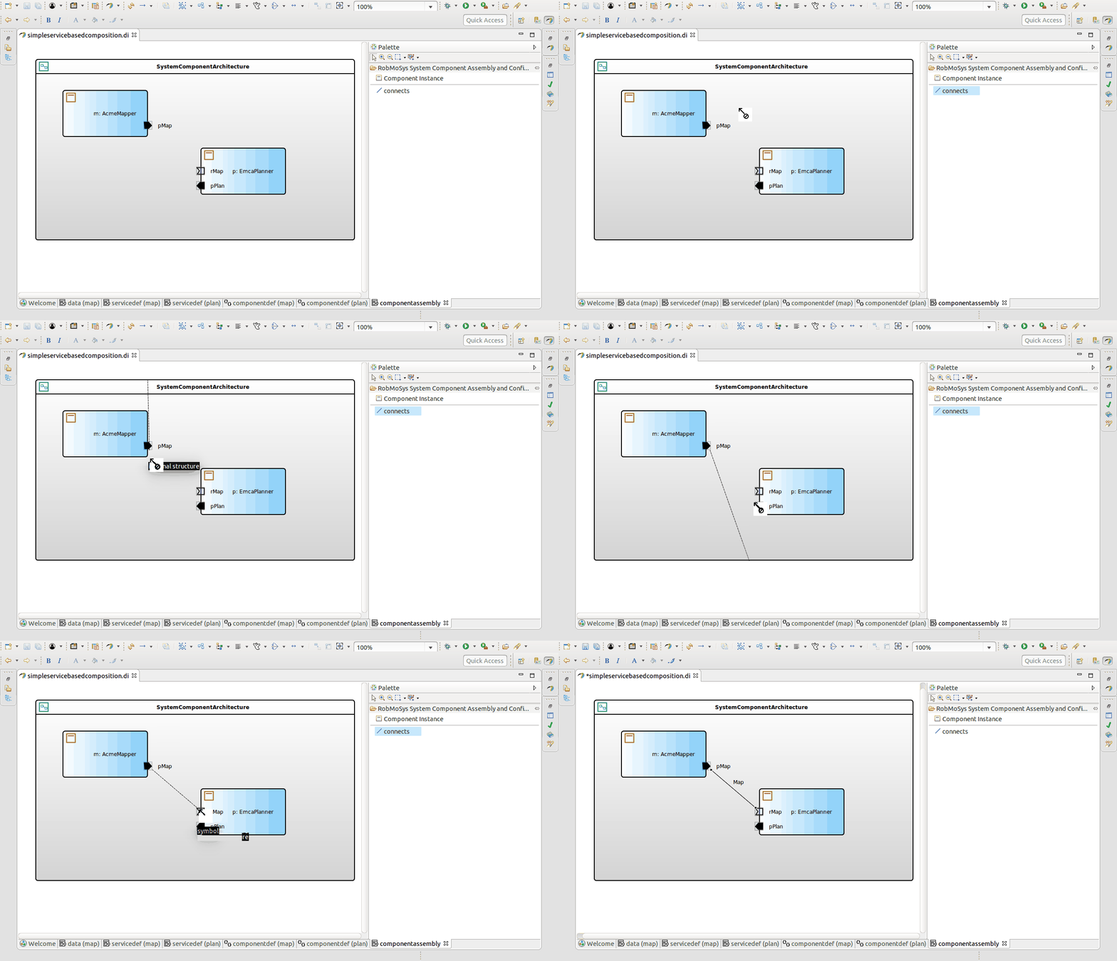
Connections between component instances can be drawn by using the connects item from the system component architecture palette.
First, select connects from the palette. Then point and click the source and target component ports to be connected. Note that the connection is only possible if
- both source and target elements are component ports
- both ports provide/require compatible services. In other words, for 2 connected (component) ports, the type represented by a component service must be instance-of the same service definition.
http://www.robmosys.eu/wiki-sn-02/baseline:environment_tools:getting_started_with_papyrus4robotics

